
eine Nachricht hinterlassen
Wenn Sie an unseren Produkten interessiert sind und mehr Details erfahren möchten, hinterlassen Sie bitte hier eine Nachricht. Wir werden Ihnen so schnell wie möglich antworten.


Deploying a robust physical infrastructure is arguably the most capital-intensive phase of any telecommunications project. As network operators globally accelerate their fiber rollouts to support 5G backhaul, smart city grids, and gigabit residential broadband, the physical distribution nodes connecting the central office to end-subscribers face unprecedented stress. At the heart of this outside plant (OSP) network lies the Fiber Distribution Cabinet (FDC) or Fiber Distribution Hub (FDH).
Choosing the wrong hardware for these critical junctions can lead to severe optical signal degradation, catastrophic water ingress, and extensive network outages during extreme weather events. The right choice, however, dramatically reduces long-term operational expenditures (OPEX) and simplifies future network scaling. Below, we dissect the critical engineering factors—from geographic environmental challenges to internal splitter modularity—that network architects must evaluate to secure a resilient, future-proof optical network.
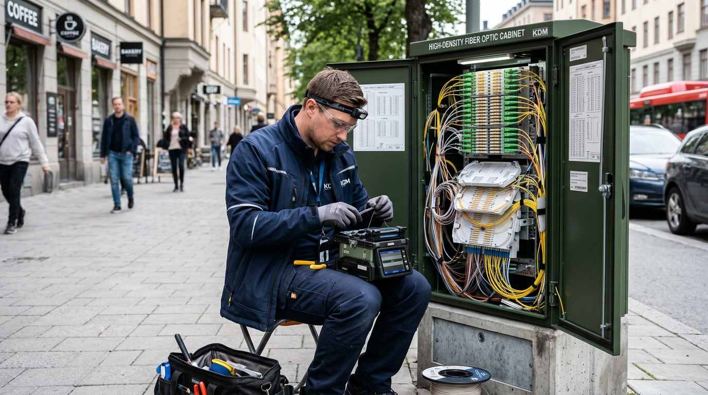
The geographic location of your deployment should instantly narrow down your structural material choices. Telecommunications cabinets placed outdoors are exposed to relentless UV radiation, severe temperature fluctuations, and highly corrosive elements over a lifespan of 15 to 20 years. Network architects generally choose between two primary materials, depending on the specific environmental threat model of the deployment region:
Capacity planning is a delicate balance between managing current capital expenditure (CAPEX) and ensuring future scalability. Over-provisioning wastes budget, while under-provisioning leads to rapid infrastructure bottlenecks. If you are deploying an FTTB (Fiber to the Building) architecture in a mid-rise residential complex or an enterprise campus edge, a compact wall-mounted FTTH fiber termination box supporting 48 to 96 cores might be perfectly sufficient and cost-effective.
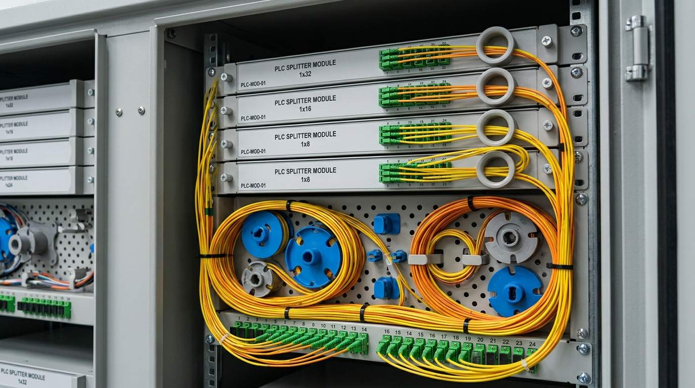
However, for street-level FDHs managing thousands of residential connections across suburban neighborhoods, a 288 or 576-core cabinet is mandatory. Crucially, engineering teams must specify cabinets that support modular PLC (Planar Lightwave Circuit) splitters (e.g., 1:8, 1:16, 1:32 cassette or plug-in modules). This specific modularity allows telecom operators to gradually scale up the optical distribution network (ODN) in phases without interrupting live traffic, thereby preserving optical budgets and deferring costs until subscriber demand dictates expansion.
Regardless of how sophisticated your optical switches and core routers are, a single drop of water on a mated connector inside a street cabinet can cause massive insertion loss and bring down an entire network segment. For any outside plant application, you must insist on a certified IP65 waterproof fiber optic enclosure or higher. This strict rating guarantees that the internal splicing trays, splitters, and pigtails are completely protected against powerful water jets, heavy rainstorms, and fine dust ingress.
Furthermore, pay close attention to the physical routing guides designed into the cabinet's chassis. As fiber densities increase, cable congestion becomes a primary cause of network failure. The cabinet must feature dedicated slack storage spools, robust cable clamping mechanisms for heavy incoming trunk cables, and strictly enforced bend-radius controls. Maintaining a minimum bend radius of 30mm across all internal routing paths is essential to prevent optical signal attenuation (macro-bending) across the distribution matrix.
To assist your procurement and engineering teams in making the right choice, reference the configuration matrix below. It aligns standard hardware architectures with specific deployment scales and geographic requirements.
| Cabinet Architecture Type | Typical Core Capacity | Recommended Material | Primary Application Scenario |
|---|---|---|---|
| Compact Wall/Pole Mount Box | 24 to 96 Cores | PC+ABS / SMC | FTTB, Rural Edge Networks, Enterprise Buildings |
| Medium Capacity Street Cabinet | 144 to 288 Cores | SMC / Galvanized Steel | Suburban FTTH, Campus Network Aggregation |
| High-Density Cross-Connect Hub | 576+ Cores | SMC / 304 Stainless Steel | Urban Core Networks, Dense Metro Fiber Backbones |
Q1: What is the primary difference between a Fiber Distribution Cabinet (FDC) and an Active Telecom Cabinet?
A: An FDC is a completely passive infrastructure node. It requires no electrical power, air conditioning, or active cooling systems. Its sole purpose is to securely house passive optical components like fusion splices, pigtails, and optical splitters. In contrast, an active cabinet houses powered equipment like rectifiers, BBUs, and batteries, requiring rigorous thermal management.
Q2: Can I upgrade the splitter capacity in the cabinet at a later stage?
A: Yes. Professional distribution cabinets utilize a highly modular design featuring standard slot-in PLC splitter trays or plug-in cassettes. This allows network engineers to initially deploy a fraction of the capacity to minimize CAPEX, and easily plug in additional 1:16 or 1:32 splitters dynamically as subscriber demand in that specific neighborhood grows.
Q3: How does SMC material handle extreme temperature variations compared to metal?
A: SMC (Sheet Molding Compound) is exceptionally resilient to temperature extremes. Unlike metal, which highly conducts heat and can cause massive internal temperature spikes (leading to condensation and fiber degradation), SMC acts as a thermal insulator. It maintains a much more stable internal micro-climate and will never rust or corrode, making it far superior for harsh outdoor deployments.
eine Nachricht hinterlassen
Scan to Wechat :

Scan to WhatsApp :